01
PoE Clocks
Approved clock configurations and quantities assigned to installation locations.


Plan synchronized time displays around a coordinated Ethernet power and network connection. HC Electronics helps configure PoE clock systems by matching clock locations, compatible power-sourcing equipment and the required time reference into one project specification.
Start with the network equipment you already operate or include new infrastructure in the project plan. The proposed installation should account for every powered clock connection, the capacity supporting it and the work required at the site.
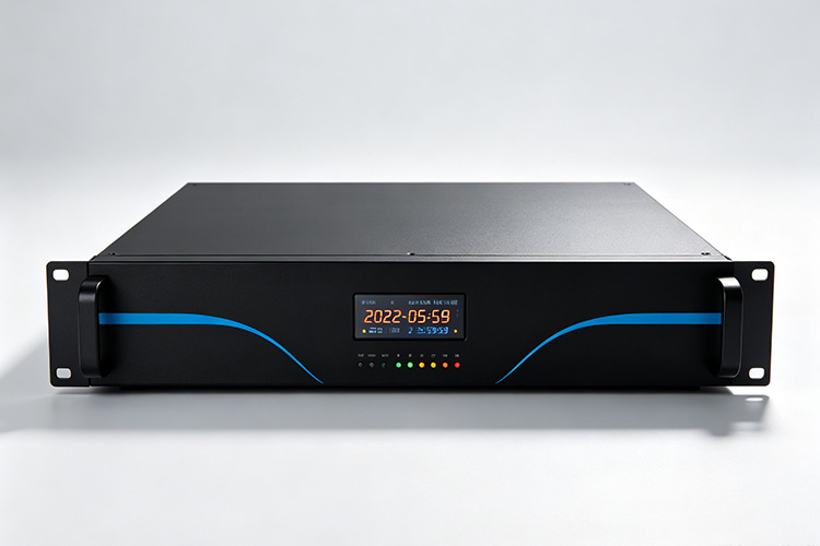
A PoE clock system combines receiving clocks, Ethernet cabling, suitable power-sourcing equipment and an accessible network time service. Power and data share the connection to each compatible clock, but PoE supplies electrical power—not the time reference itself. The selected clocks still need their supported timing service, such as NTP.
Bring these elements together in the project equipment schedule.
Approved clock configurations and quantities assigned to installation locations.
Compatible switches or injectors, their available connections and the power assigned to the clocks.
An approved existing service or a separately specified server where one is required.
Cable routes, patching, outlets and the equipment-room connection serving each display.
Any required backup arrangements for the equipment supporting display operation and synchronization.
Responsibility for supplying, mounting, connecting, configuring and accepting each part of the installation.
A new time server is not automatically part of every PoE project. Identify whether the clocks will use a suitable existing service or whether reference equipment must be included in the quotation.
An unused switch port is not proof of available PoE capacity. Review both the power supported by each assigned port and the total budget available across the connected equipment. A switch can deny power when a device’s allocation would exceed its available budget.
Prepare the power calculation for each serving switch or documented shared power group. Include clocks alongside any other powered devices using that capacity, and reserve an agreed allowance for planned additions.
Use the allocation method applicable to the selected switch and clock combination. Allocated power can differ from measured operating consumption, and the requirement at the supplying port must account for cable losses. An occasional low-power reading should not replace the documented design requirement.
Record the calculation alongside the port assignments. Where the project includes different clock sizes or assemblies, use the appropriate requirement for each configuration rather than multiplying every location by one assumed wattage.
Before equipment approval, have the network team confirm the capacity remaining after the proposed installation—not just the capacity before the clocks are added.
Connect each clock location to a defined switch or injector position on the project drawing. Include the route through patch panels and outlets so the planned connection reflects the complete installed channel.
Conventional copper Ethernet connections are generally designed within a 100-metre channel limit. A longer building route therefore needs a reviewed infrastructure solution rather than an assumption that an extended cable will provide acceptable power and connectivity.
For existing cabling, arrange verification of its condition and suitability for the proposed equipment. Identify connections that require replacement or new testing before the clocks are delivered.
Keep a consistent reference between the clock location, cable label and assigned equipment port. This gives the installation and maintenance teams a practical way to trace an affected display without treating every cable as an unidentified connection.
PoE allows compatible clocks to receive power from equipment that can be supported by an uninterruptible power supply. The backup arrangement must be sized for the actual connected load and required operating duration.
For your project, distinguish two objectives: keeping the displays powered and keeping their time reference accessible. Include the necessary network path and time-source equipment in the continuity review rather than protecting only the clock-serving switch.
Specify which areas must remain operational during an interruption and for how long. Have the responsible power and network teams identify the equipment that supports those areas.
Also agree how planned switch maintenance will be handled. Ask whether the selected equipment maintains PoE during the particular restart or update operation being considered; do not assume uninterrupted clock power during every maintenance event.
A successful test of one clock does not complete acceptance of a fully populated PoE installation. Agree a site test using the planned clock quantities and representative loads from other devices sharing the supplying equipment.
Verify that each assigned connection receives power, that the clock reaches its approved time service and that the display meets the agreed timing requirement. Keep power delivery and synchronization as separate acceptance checks.
Include a controlled restart of the serving equipment during an approved maintenance window where recovery is part of the requirement. Establish whether all planned clocks receive power and return to accepted operation without manual intervention. PoE allocation after a restart can be affected by insufficient available capacity.
Record any power-denied indications, unexpected resets or unsuccessful synchronization alongside the relevant location and port. Resolve those findings before signing off the affected area.
The handover record should include the accepted power allocation, installed port map and results of the agreed operating and recovery tests.
Request a bill of materials that separates the clock package from retained or separately purchased infrastructure. Identify who supplies the PoE switches or injectors, network cabling, mounting accessories, time-source equipment and any backup power.
Ask for installation labour, network configuration and commissioning responsibilities to be stated independently of hardware supply. A coordinated equipment proposal should not leave either party assuming that another will provide an essential component or service.
For phased projects, identify the first-stage installation and later additions separately. Include the infrastructure changes needed for each stage so a later extension is not priced as clocks alone when additional powered connections are also required.
They can be considered in the same equipment plan, subject to compatible power requirements, sufficient capacity and your organization’s network policies.
Have the network team review the combined allocation and any configured power priorities. The assessment should cover all devices sharing the supply, not just the new clocks.
The project can be assessed around customer-specified power equipment. Provide the switch or injector models, fitted power-supply details and available PoE capacity so compatibility can be reviewed with the proposed clocks.
Where different suppliers are involved, agree who verifies the combined configuration and who handles any changes identified during testing. List customer-provided equipment clearly in the accepted proposal.
Send HC Electronics the proposed clock locations, quantities and available Ethernet connections. Include the serving switch or injector models, existing PoE loads and any required backup duration.
Identify the network time service available, planned installation stages and the equipment or site work you expect to be included. We will review the requirements and discuss a PoE clock system proposal covering clock configurations, power capacity, connection planning and acceptance scope.