

GPS Master Clock System
Establish a GPS-based master reference for clock sections that need to operate from an agreed source of time. HC Electronics reviews GPS master clock system requirements as part of its facility timing projects, bringing reference equipment and compatible distribution connections into a defined configuration for synchronized clock systems.
For a project involving existing controllers, new clock groups or different timing interfaces, start with the connections between those sections. The proposed arrangement should identify which equipment establishes the reference, which equipment distributes it and what can remain in service.
Discuss Your GPS Master Clock Project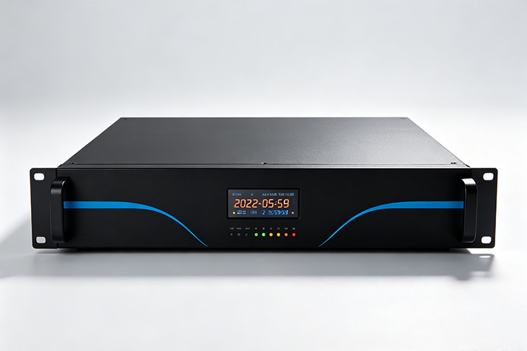
A GPS Master for Separate Clock Sections
A GPS-referenced master clock can supply timing information through supported distribution outputs. The available output formats depend on the master clocks equipment; receiving a GPS reference does not establish compatibility with every downstream clock connection.
For your project, distinguish clocks connected directly to the master from sections served through a retained local controller. Where a local controller accepts a suitable external reference, assess whether it can continue operating its existing clocks while following the proposed GPS master.
This allows the integration review to focus on the connection between clock sections, rather than starting with an assumption that every display must be replaced.
Each proposed connection must have a confirmed receiving interface. Additional converters, transmitters or distribution units belong in the agreed configuration only where their compatibility has been established.
Define Where the Master Delivers Time
Prepare a connection schedule showing where responsibility passes from the GPS master equipment to each receiving section. Associate every connection with the equipment accepting it and the part of the installation it serves.
| Project Connection | What to Agree |
|---|---|
| GPS reference to master equipment | The receiving arrangement included with the project and the master input it supports. |
| Master to retained controller | The controller’s documented external-reference input, accepted format and required operating settings. |
| Master to a new clock group | The approved distribution output and the receiving equipment assigned to that group. |
| Master through an intermediate device | The function of the additional equipment and its verified input-to-output compatibility. |
| Central status to the operating team | The information available, how it is accessed and who responds when the reference condition changes. |
| Provision for a later section | The reserved connection, remaining capacity and conditions that must be met before expansion. |
Use this schedule to distinguish required connections from optional ones. A future interface can be included as a separately priced provision without being mistaken for an active part of the initial installation.
The project drawing should also identify whether GPS reception is integrated into the master equipment or provided by a separate receiver. Keep the approved receiving package associated with the central equipment it serves.
Review Existing Controllers as Reference Recipients
For a retained controller, provide the documentation for its external synchronization input, not only the outputs that drive its clocks. Identify how it currently obtains time and whether that operating mode can be changed.
Assess the controller in the role it will perform after integration. Ask whether it can accept the proposed reference while preserving the clock-driving functions required by its existing section.
Where the controller cannot accept the available reference directly, request a documented alternative. The proposal should distinguish an approved interface arrangement from a section that requires controller replacement.
Keep any retained local settings visible in the project record. These may include correction schedules, clock-group assignments or operating restrictions. Identify which settings must remain unchanged and which need adjustment when the controller begins following the central master.
Approve the retained equipment by model and configuration. Similar controller names or matching connectors should not be used as the basis for accepting an unverified connection.
Keep the Reference Direction Clear
Record the normal source assignment for the central master and every downstream controller. For network-connected sections, avoid a circular dependency in which equipment ultimately relies on its own distributed time as the upstream reference. NTP implementations include checks intended to reject such timing loops.
Where a local controller already has another reference, decide whether it will be removed, retained as an approved alternative or left outside the new arrangement. Specify the source-selection behaviour required rather than assuming that connecting the GPS master automatically changes the controller’s preference.
The time presented through each connection also needs an agreed interpretation. NTP distributes time based on UTC; local display adjustments should therefore be distinguished from the network reference itself.
For each section, identify where any local-time adjustment takes place. Have the integration review check that an offset is not unintentionally applied twice, once upstream and again in the receiving equipment.
Separate Central and Local Operating Responsibilities
Define who maintains the GPS master reference and who maintains each connected clock section. A shared source should have an agreed owner for configuration changes, reference investigations and planned maintenance.
Request the status information needed to distinguish a central reference problem from a problem affecting one receiving section. Ask what can be observed at the master, what must be checked at a local controller and what requires inspection of the clock displays.
Where continued local operation is required during central maintenance, include that requirement in the configuration review. Specify the permitted interruption and the conditions under which a section may use an alternative reference.
Do not assume that a second controller, spare connector or additional power supply provides an independent timing path. Any required backup arrangement should identify the components involved and the failure condition it is intended to address.
Verify the Connections as an Integrated System
Agree acceptance at both the master outputs and the receiving sections. A GPS reference alone does not provide a performance guarantee for the completed installation; receiving equipment and operating conditions affect the time delivered by the equipment, as noted in published GPS accuracy information.
For each approved connection, establish that the receiving controller or clock group accepts the designated reference. Check the resulting time at that section against the agreed tolerance, rather than relying only on a correct reading at the central master.
Then evaluate the required connections together. Confirm that enabling another section or carrying out an agreed configuration change does not prevent previously accepted sections from operating as specified.
Include a controlled source-selection test where an alternative reference forms part of the project. Record which reference each section accepts during the test and how it returns to its normal assignment.
Keep the accepted connection schedule, source assignments and test results together. These records define the integrated arrangement and provide a clear basis for reviewing later additions.
Specify the Integration Package
Request a quotation that separates the central GPS reference package from the work needed to connect individual clock sections.
The central package should identify the master equipment and applicable receiving accessories. Each downstream connection should identify any supplied interface equipment, configuration work and changes required to retained components.
Make the limits of supply explicit. Antenna installation, equipment-room connections, modifications to existing controllers and site acceptance may involve different parties. Assign those responsibilities before the equipment order is finalized.
Where a connection has not yet been verified, have it recorded as an unresolved requirement rather than included as an assumed capability. This keeps the accepted scope tied to equipment combinations that can be demonstrated.
Request a GPS Master Clock System Proposal
Send HC Electronics an inventory of the clock controllers and distribution sections you need to coordinate. Include their available reference inputs, current source assignments and any equipment that must remain unchanged.
Add the required GPS receiving arrangement, proposed new clock sections and operating restrictions during integration. We will review the requirements and discuss a project configuration with defined reference connections, compatible equipment and an agreed acceptance scope.
Request a GPS Master Clock System Quote