

Wired Synchronized Clock System
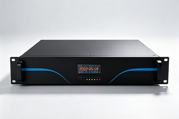
Connect your clock locations through dedicated timing circuits planned around the building’s cable routes. HC Electronics supports wired synchronized clock system projects that combine central timing equipment, compatible receiving clocks and the connections needed throughout the installation.
For new construction, coordinate the clock circuits with the planned electrical work. For refurbishment, establish which existing routes can be retained and which sections need modification before the equipment package is finalized.
Plan the Installation Circuit by Circuit
Begin with the route between the controlling equipment and the clocks it will serve. Identify the rooms, corridors and floors connected to each circuit, including junctions and any intermediate distribution equipment.
A useful project drawing shows more than clock positions. It should identify how the cable reaches those positions, where connections remain accessible and which equipment supplies each section.
Prepare a circuit schedule alongside the floor plan.
| Circuit Record | Information to Establish |
|---|---|
| Originating output | The master-clock or distribution output assigned to the circuit. |
| Connected clock positions | Location references, receiving-clock configurations and quantities on that connection. |
| Cable route | Estimated installed length, cable specification and accessible junction locations. |
| Connection arrangement | The approved layout of the main cable, clock connections and any separate branches. |
| Operating power | The supply serving the clocks and whether power is distributed centrally or provided locally. |
| Circuit-end requirements | Any termination, protection or connection components required by the selected equipment. |
Use the schedule to connect equipment quantities with actual installation work. Where a route has not yet been surveyed, identify it as an item requiring confirmation rather than including an assumed cable allowance.
Match the Wiring Layout to the Selected Equipment
The cable layout must suit the timing interface—not simply the shortest route between rooms. For example, RS485 installations commonly use a main cable with short connections to individual devices. Long branches or arbitrary junction arrangements can affect signal quality.
Where an RS485 configuration is proposed, have the route reviewed against the selected controller, receiving clocks and communication settings. Do not apply that layout automatically to another type of clock circuit.
Identify any point where the building layout requires separate distribution sections. Additional interface equipment should be specified only where its purpose and compatibility have been established.
Keep junction locations visible on the drawing. Where an installer proposes a routing change, review its effect on the electrical arrangement before treating it as an equivalent substitute.
Account for Signal Loading and Clock Power
Assess the completed circuit with its intended equipment connected. In an RS485 arrangement, the electrical load presented by receivers and associated circuitry affects how many devices a driver can support. A total clock count alone is therefore not a complete capacity calculation.
Document the permitted receiving load for each proposed section. Include the actual clock configurations and any distribution components, rather than applying one assumed capacity to the entire building.
Review operating power separately. Identify whether the clocks receive power through the selected clock circuit or require another supply, and show that arrangement in the project documents.
For centrally supplied low-voltage clocks, request a voltage-drop assessment for the installed cable lengths and intended simultaneous load. Specify verification at the electrically most demanding clock positions—not only at the power source.
Where different display sizes are included, use the appropriate electrical requirements for each version. Agree any expansion allowance against both the timing circuit and the supply that supports it.
Survey Existing Wiring Before Committing to Reuse
For refurbishment work, trace each proposed retained route from its source to its connected clocks. Include junction boxes, abandoned branches, changes in cable type and sections that cannot be accessed for inspection.
Have the responsible installer verify the wiring against the new configuration. Request the applicable cable-condition and connection checks using procedures suitable for the installed equipment.
Separate the findings into sections that can be retained, sections requiring modification and sections requiring replacement. This gives the quotation a defined scope without assuming that all existing wiring is either usable or unsuitable.
Where documentation is incomplete, arrange the survey before fixing the final installation price. Keep unresolved routes visible in the project record so they are not mistaken for approved connections.
Review Electrical Boundaries and Maintenance Access
Identify cable routes that cross between buildings, separate electrical areas or locations containing substantial electrical equipment. For RS485 links, differences in ground potential and electrical interference can affect operation; isolation and protection requirements need an engineering review appropriate to the site.
Include any approved protective or isolating equipment in the system configuration. Do not assume those functions are built into every controller or receiving clock.
Plan accessible points for inspection and authorized maintenance. Agree how a section can be disconnected, which clocks would be affected and what must be checked before it returns to service.
For clocks mounted above ceilings or in restricted areas, identify the access arrangements before installation. Keep the clock location, connection point and circuit identification consistent across drawings and equipment labels.
Verify the Installed Circuits Under Operating Conditions
Agree the site acceptance procedure before the cable work is completed. The checks should establish that the installed wiring supports the approved equipment configuration, not merely that individual clocks work on a short test connection.
Begin with the installer’s required cable and connection checks. Follow the equipment documentation when determining whether electronics must be disconnected during testing.
After connection, verify synchronization at the locations assigned to each circuit. Include the ends of longer runs, different connection sections and any area where the route changed during installation.
Test with the intended clock load connected. Check the applicable operating voltage, successful time reception and displayed-time agreement against the project’s acceptance criteria.
Where restart or sectional maintenance forms part of the requirement, evaluate it using an agreed procedure. Record the affected circuit, expected response and result, and resolve outstanding findings before that section is accepted.
Make the Quotation Match the Cable Plan
Request an equipment and installation breakdown tied to the approved circuit schedule. The package should identify the central controller, receiving-clock quantities, required distribution components and the power arrangement for each section.
Cable supply, containment, junction work, connections and building repairs should have clearly assigned responsibilities. Identify whether these items are supplied by HC Electronics, the project integrator or the site contractor.
Keep survey work and changes to existing wiring separate from the supply of new clocks. Where a route remains unverified, state how the resulting work will be assessed and approved.
At handover, retain the final circuit drawings, connection records and site test results. Mark changes made during installation so later maintenance uses the completed wiring arrangement rather than the original proposal.
Wired Clock System Project Questions
Can the cable work be completed before the clocks arrive?
Agree a cable-installation specification and inspection stage with the project team. Identify cable types, routes, connection positions and the access that must remain available for fitting the equipment.
Record the completed cable checks before closing inaccessible areas. Final acceptance should still include the connected clocks operating on their actual circuits.
What needs reviewing when a circuit is extended to additional clocks?
Review the added cable length, receiving load and operating-power requirement. For an RS485 bus, extending the physical line may also change the required RS485 termination position or arrangement; termination must suit the completed circuit.
Approve the extension against the installed equipment, update the circuit drawing and recheck the affected section after the additional clocks are connected. Do not treat an unused cable end as proof of available expansion capacity.
Request Your Wired Synchronized Clock System Configuration
Send HC Electronics the building plans, clock quantities and available information about existing cable routes. Identify the controlling equipment you intend to retain, the locations requiring new wiring and any restrictions on installation access.
Include planned additions and the site work you expect to be included. Request a wired synchronized clock system proposal covering the equipment combinations, circuit layout, electrical requirements and acceptance of the installed connections.