72 MHz Radio Time Synchronization
72 MHz radio time synchronization uses a radio-frequency carrier to distribute encoded timing information from a transmitter to receiving clocks.
The transmitter obtains a reference time, prepares a timing message and sends it through the radio channel. Compatible receivers recover the message and use its defined timing information to correct their clocks.
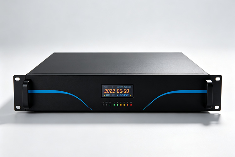
What 72 MHz Describes
The frequency identifies the radio carrier, not the rate at which the displayed clock is updated.
Neither value specifies the timing-message rate, the accuracy of the reference or the uncertainty of the receiving clock. Those properties depend on the complete communication and timing design. See wireless time synchronization principles for the broader timing-message process.
From Reference Time to Radio Transmission
The transmitter needs an upstream time reference. A dedicated radio timing design may obtain that reference from satellite reception or an NTP service.
The radio stage then distributes timing data using its own encoding and transmission format. The reference source and radio carrier perform separate functions: one establishes time, while the other carries information about it.
Reference Source
Satellite reception or NTP service establishes timeRadio Transmitter
Encodes timing data and sends it on the 72 MHz carrierReceiving Clocks
Recover the message and correct local timeHow a Receiver Recovers Time
A typical receiving process includes:
The exact modulation, frame layout and validation method depend on the radio protocol.
The timing relationship is particularly important. A frame that takes time to transmit must define whether its time value refers to the beginning, end or another point in that transmission.
Carrier Frequency and Message Format
Two transmissions can occupy similar frequencies while carrying completely different information.
A receiver needs more than frequency alignment. Its demodulator and decoder must understand the transmitted symbols, data rate, frame structure and timing convention.
The technical meaning of “72 MHz” therefore stops at the radio-frequency layer. It does not define a universal clock synchronization protocol.
Broadcast Timing and Receiver Feedback
In a one-way broadcast design, multiple clocks can listen to the same transmission. Adding listeners does not require the transmitter to create a separate timing exchange with each one.
However, the transmitted signal alone provides no confirmation that every receiver accepted the update. Receiver feedback requires a return communication path and an application that supports it.
Timing Error Through the Radio Path
Potential error exists at several points:
| Stage | Possible Contribution |
|---|---|
| Reference input | Error in the transmitter’s source time |
| Transmission scheduling | Variation between the intended and actual timing event |
| Radio propagation | Travel time from transmitter to receiver |
| Receiver processing | Delay or uncertainty in detecting the reference event |
| Local timekeeping | Drift between accepted updates |
At ordinary building distances, signal travel time is short. Message scheduling and receiver interpretation can still matter substantially, so carrier frequency alone cannot establish end-to-end accuracy.
Lost Frames and Continued Timekeeping
An incomplete or invalid frame should not become a new timing reference. Between accepted frames, the receiving device relies on its own timekeeping behavior.
Repeated transmissions provide further opportunities to acquire valid time, but a missed transmission does not reveal how much a particular clock has drifted.
Is a 72 MHz product description enough to prove legal radio use?
A 72 MHz description alone does not establish permission to operate radio equipment at a particular site. Check the exact transmitter and receiver, destination-market requirements and applicable operating conditions with the supplier and relevant local authority before deployment.
For other project checks, see the synchronized clock planning FAQs.
Plan Your Radio Time Synchronization System
HC Electronics designs and supplies time synchronization equipment, including reference time servers, radio transmitters and receiving clocks for buildings and campuses.
Share your site layout, clock quantity and reference source requirements, and our engineers will recommend a suitable configuration. Learn more about HC Electronics or visit our contact page.

Contact us via WhatsApp